

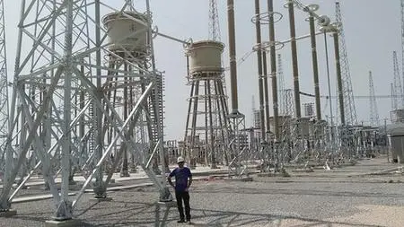
Earthing Design Calculation for 380/132/11kV Substation
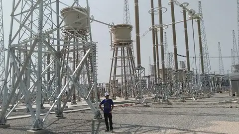
Earthing Design Calculation for 380/132/11kV Substation
MP4 | Video: h264, 1280x720 | Audio: AAC, 44100 Hz
Language: English | Size: 1.82 GB | Duration: 2h 53m
MP4 | Video: h264, 1280x720 | Audio: AAC, 44100 Hz
Language: English | Size: 1.82 GB | Duration: 2h 53m
Learn directly from a Global Professional Electrical Engineer with +17 years of Field Experience , Protection & Control
What you'll learn
From Scratch , Complete Earth Design Calculations of 380/132/11kV Substation
What Parameters are required fro Earthing design Calculations of Grid
Step by Step Guide of each step
Actual Substation Earth Design Calculations explained
Requirements
Basic Understanding
Description
Dear All,
I have prepared this course based on actual design calculations for the actual 380/132/11kV Substation.
Explained in detail topics step by Step.
Introduction
Collecting information of substation, total line and transformer, etc
Collecting Network Data
Explaining Short Circuit Level, Fault Clearance time, Thermal Time
Collecting Data at Site for Specific Soil Resistivity
AEMC® - Wenner Soil Resistivity Testing Explained - Using 6472
Difference between resistivity and Resistance
How to Calculate Thermal Design of earthing electrode and conductors
Calculating Area for Conductor as per IEEE Std 80 2000
Discussing Fusing temperature, Ambient temp, Material Constant, Thermal Capacity, Thermal Coefficient
Discuss the Design Software Used for Calculations
Introduction to SES CDEGS _ FCDIST - Getting Started
Calculation of Grid Earth Resistance
Standard describing Minimum Requirement of Earth Resistance
Tolerable Touch and Step Potential
The formula for Step & Touch Potential
Determination of Maximum Grid Current
Determination of Ground Potential Rise
Design of earth grid with respect to touch and step voltages
Single-Electrode/Touch Voltages/Worst Spherical
Design Criteria for step & Touch Potential
Foundation Earth Electrodes
Indoor Earthing System
Outdoor Earthing system
Input to software
The grounding system in the substation is very important. The functions of grounding systems or earth mat include:
Ensure safety to personnel in substations against electrical shocks.
Provide the ground connection for connecting the neutrals of stat connected transformer winding to earth ( neutral earthing ).
Discharge the overvoltages from overhead ground wires or the lightning masts to earth. To provide a ground path for surge arresters.
Provide a path for discharging the charge between phase and ground by means of earthing switches.
To provide earth connections to structures and other non-current carrying metallic objects in the sub-station (equipment earthing).
In addition to such a grid below ground level, earthing spikes (electrodes) are driven into the ground. They are connected electrically to the earth grid, equipment bodies, structures, neutrals, etc. All these are connected to the station earthing system by earthing strips.
If the switchyards have a soil of low resistivity, the earth resistance of the earthing system would below. If the soil resistivity is high, the mesh rods are laid at closer spacing. More electrodes are inserted into the ground.
Thanks
Muhammad Kashif
Who this course is for:
Student, Engineer, Professionals