


CAMWorks 2025 SP2 for SolidWorks
CAMWorks 2025 SP2 for SolidWorks | 2.0 Gb
Languages Supported: 中文 Simplified, 中文 Traditional, Français, Deutsch, Italiano,
日本語, Polski, Português-Brazilian, Русский, Español, Türkçe, 한국어, Čeština
Languages Supported: 中文 Simplified, 中文 Traditional, Français, Deutsch, Italiano,
日本語, Polski, Português-Brazilian, Русский, Español, Türkçe, 한국어, Čeština
HCLSoftware has released HCL CAMWorks 2025 SP2 is an intuitive, feature-based CAM software that helps to increase productivity using best-in-class technologies and adaptable automation tools to maximize CNC machining efficiency.
What' new in CAMWorks 2025
CAMWorks 2025 comes packed with new enhancements and improvements which have been developed by considering the latest machining trends in the market. You can get the details of the new features from the ‘What’s New’ document.
1.CW-137318 CW-137033 CW-136898 CSR-28704 CSR-28702 CSR-28590 CSR-28567 Assembly In CAMWorks Assembly mode, when importing patterned feature into the assembly file, rapid moves become inconsistent and therefore incorrect. The same CAM data in part files shows correct rapid moves, but changes unexpectedly in the assembly.
2. CW-137034 CSR-28615 Assembly For the specific Assembly with multiple parts, the ‘Select All Faces’ option fails to create the correct Multi Surface feature when using the ‘Insert Multi Surface feature’ option. The faces for the first part are selected correctly, but not for any succeeding parts.
3. CW-137031 CSR-28606 Operation Tap pitch and feedrate are incorrect for Turn Setups. When using a 1/4-20 UNC tap, the Tool Parameters for the Turn Tap operation do not match those in the TechDB, unlike the Mill Tap operation where they do match. Additionally, Tool Comments differ between Turn Tap and Mill Tap operations, leading to inconsistencies.
4. CW-136688 CSR-28516 UIF In the Spanish language version of CAMWorks 2025, the translation for some of the parameter names under the ‘Face Finish’ and ‘Thread’ tabs of the Operation Parameters dialog box are incorrect.
5. CW-136673 CSR-28467 Toolpath When the specific programmed Mill part is opened in CAMWorks 2025 SP1 or any previous version run on Windows 10, an incorrect angled Feed Move is visible for its Contour Mill operation. However, this incorrect move is removed when previewing the part from the Operation Parameters dialog box or regenerating the toolpath or when run on Windows 11.
6. CW-136588 CSR-28532 UIF In Turn mode, for Face Rough operations, the Preview window images for ‘Start Length’ and ‘End Length’ are incorrectly displayed when the respective fields are selected under the ‘Feature Options’ tab of the ‘Operation Parameters’ dialog box.
7. CW-136341 CSR-28448 Graphics In Turn and Mill-Turn modes, in certain instances, multiple CAMWorks graphics display area issues are observed related to random displays of double tools, incorrect stock, disappearing chucks, and other graphical anomalies.
8. CW-136033 CSR-28359 UIF In CAMWorks, when the Stock display option is set to ‘Translucent’, the Stock Manager randomly changes the stock already assigned within CAMWorks. This is observed when opening and closing various tabs after selecting or highlighting the Stock Manager.
9. CW-135914 CSR-28410 UIF For the specific Turn part, the Turn Thread definition in CAMWorks changes its pitch value unexpectedly when closing the Thread Feature definition without making any changes. This causes incorrect Thread associations and pitch values in the output G-code, leading to faulty NC code for machining parts.
10. CW-135886 CSR-28394 Feed Speed In CAMWorks 2025 version, the Tap Pitch for a 3/8-24 Fine Thread Tap is incorrectly calculated as 0.0394 Inches per revolution instead of 0.0417 Inches per revolution. Although TechDB displays the correct pitch, the operation uses the wrong value, leading to errors in G-code output.
11. CW-135838 CSR-28333 Toolpath In Turn mode of CAMWorks 2025, when a User Defined Tool is used for machining a Face Feature, the Face Finish toolpath generated is incorrect. This issue is not observed in any previous versions of CAMWorks.
12. CW-135782 CSR-28362 System Opening the specific Mill part causes CAMWorks, which is loaded as an add-in within SOLIDWORKS, to crash.
13. CW-135740 CSR-28343 System Opening the specific Assembly file causes CAMWorks, which is loaded as an add-in within SOLIDWORKS, to crash.
14. CW-135726 CSR-28338 Assembly In CAMWorks 2025, for the specific assembly file, the Mill feature created using an assembly sketch is initially incorrect but gets generates correctly upon Rebuild.
15. CW-135725 CSR-28326 Toolpath For Multiaxis operations, the Feedrate changes require multiple attempts before XY feeds are correctly updated in the Cutting Parameters dialog box invoked from Edit Tool Parameters window. Initial changes fail to reflect in the Preview window or posted code until the process is repeated and the operation is regenerated. This issue is causing delays and inefficiencies.
16. CW-135629 CSR-28284 UIF When using any user-defined Tool Insert or/and Holder, the B axis Incremental Angle does not display in the Tool Preview window or during StepThrough Toolpath execution. This causes inaccuracies in the simulation and preview.
17. CW-135520 CSR-28266 API When the "ChangeFeatStrategy.swp" macro is executed for the specific Mill part, an error message that states “A serious error occurred during macro playback. Perhaps the macro was not planned in the correct context. The system could be in an unstable state now.” If the macro is run for a second time, CAMWorks crashes.
18. CW-135014 CSR-28112 System For the specific Turn part, when creating a new Sub Spindle operation, CAMWorks crashes. This issue is observed only when the ‘Name operation on creation’ checkbox option within the New Sub Spindle Operation dialog box is checked.
19. CW-134849 CSR-28087 Toolpath For the specific Mill part, when the step over value is set to exactly 15% for the Rough Mill operation, it results in generation of incorrect toolpath with an inconsistent move. However, the toolpath generates correctly if the step over value is adjusted to less than 14.9899% or greater than 15.0011%.
20. CW-134728 CSR-28045 Toolpath For Contour Mill operations generated for Circular profiles or Hole features, checking the ‘Single Cut Depth’ checkbox option under the ‘Finish passes’ group box within the ‘Side Parameters’ dialog box generates an incorrect toolpath. The toolpath ramps down from the perimeter of the circular pocket to the next Z depth, causing gouging due to improper cutter compensation. The toolpath generates correctly if the ‘Single Cut Depth’ checkbox option is unchecked.
21. CW-134549 CSR-28031 Shopfloor For any Turn part, if the Main Spindle Coordinate System has a Z axis definition or selection by face, publishing such a part in CAMWorks ShopFloor results in incorrect display of chuck and toolpath orientation. Additionally, running the toolpath simulation in ShopFloor generates an error message about the wrong stock profile, preventing simulation. However, if the Z coordinate selection in the Main Spindle Coordinate System dialog box of CAMWorks is removed, the ShopFloor file publishes correctly, and no issues are observed.
22. CW-133948 CSR-27910 Assembly When a nested layout assembly comprising several nested parts generated using the NESTINGWorks application is opened in CAMWorks, the user is unable to select the part-level sketches present in the assembly for defining Engrave features.
23. CW-133911 CSR-27898 TechDB For the specific Mill part, when updating operation plan for a Group Hole Feature, incorrect machining depth value is retrieved from the TechDB for Center Drill operations. After saving a hole group process for chamfering, the operation depth for chamfer depth is not updated correctly after multiple updates. The issue is also observed for Countersink operations and occurs only when the operation depth criteria in TechDB is set to Countersink diameter.
24. CW-133826 CSR-27883 OPR In CAMWorks Assembly mode, editing any linked operations causes the rapid and clearance planes of the linked operations to change incorrectly. This occurs when both the clearance and rapid planes are referring to the Setup Definition and both the linked operations have different values of their setup definition in NC Planes tab of Operation Parameters dialog box.
25. CW-133825 CSR-27877 Simulation For the specific Mill part, when running simulation for a operation generated for a multi-surface feature, an error prevents the simulation from continuing. There are no gouge checks active while running the simulation. However, changing the tool quality to higher resolution, increasing the tool flute length, or selecting tool axis smoothing resolves the error.
26. CW-133812 CSR-27868 UIF In CAMWorks TechDB, when Lollipop, Dovetail, and Keyway tools are marked as inactive and saved, they still appear in the Tool Selection list when adding new tools for any operation in the CAMWorks application.
27. CW-133498 CSR-27744 Assembly For the specific Assembly file, editing Setups causes the Setup direction to flip and ignore the setup origins. This results in strange feature placements and incorrect Z direction, particularly when using assembly sketches to define origin locations.
28. CW-132981 CSR-27640 Simulation When using a spring pass for the Contour Mill toolpath with Toolpath center set to "Without Compensation", the lead-in and lead-out moves do not appear in the simulation. Additionally, lead-in and lead-out toolpaths are not seen in the simulation when the spring pass value is an odd number (E.g.: 1, 3, 5). They work fine with even numbers (e.g., 2, 4, 6, etc.).
29. CW-132224 CSR-27436 Toolpath For the specific Mill part, generating the toolpath for a Contour Mill operation with Toolpath Center and CNC compensation set to "Without Compensation" and ‘ON’ respectively leads to incorrect toolpath generation. When using a spring pass with the Single cut depth option checked, the spring pass is incorrectly generated at each depth of cut instead of only the last cut. However, if the ‘Limited look-ahead’ option is unchecked, the toolpath generates correctly.
30. CW-131961 CSR-27134 License For a specific Mill part, when using a 3 Axis Undercut license module without any 4 or 5 Axis simultaneous machining modules present, creating a Multiaxis operation with a multiaxis strategy generates an incorrect toolpath. CAMWorks generates the toolpath as 4 or 5 axes instead of restricting it to 3 axes. This behavior depends on the defaults set in the TechDB.
31. CW-130117 CSR-26795 System For the specific Mill part, re-selecting the Tool Crib in CAMWorks changes the rolling tap operation to a cutting tap operation. This is observed when editing the machine and selecting the default Tool Crib 2, causing the tool type to switch unexpectedly.
32. CW-129848 CSR-26687 Toolpath For the specific Mill part, Contour Mill toolpath generated for pocket feature generates unwanted plunge moves when the Spring passes number is applied in the Side Parameters dialog box. This results in multiple entry Drill/Hole moves, which increase with the number of Spring passes applied.
33. CW-129830 CSR-26737 Features For the specific Mill part, operations generated for Irregular Pocket do not generate complete toolpaths as other pattern irregular pockets do. When using a pattern selection with irregular pockets, certain pocket operations fail to generate toolpaths for all pockets if the tool size is set to the nominal diameter. Adjusting the tool diameter slightly can cause toolpaths for some pockets to disappear.
34. CW-129721 CSR-26626 System In CAMWorks Mill-Turn mode, selecting a Thread Strategy with Tap Cutting or Tap Rolling for any ID feature, unnecessarily adds the tools used for that operation to the Tools tree even before generating operations. However, this issue is not observed when using a Turn machine.
35. CW-129712 CSR-26518 Assembly For the Contour Mill generated for specific Assembly file, when using the "Allowance" in Depth parameters under the Contour Tab, changing the entry methods to "Entry Hole" or "Entry Drill" incorrectly doubles the depth allowance value. This issue does not occur with "None" or "Spiral" entry methods.
36. CW-127502 CSR-25929 VoluMill For the specific Assembly file, when using VoluMill Area Clearance Rest Machining operations, extra-long Z Feed/Leadin moves are added. The operation starts at the correct Z height but then moves up nearly an inch before feeding into the part. This occurs for almost every reposition. Disabling rest machining or reducing the Max Cut Amount eliminates these moves but creates unusable toolpaths.
37. CW-121070 CSR-22819 Feature For the specific Assembly, when interactively inserting a new 2.5 Axis Feature (Open Profile feature), the feature is created with wrong orientation within the assembly. The feature orientation remains incorrect despite setting the End condition to ‘Upto Stock’ and flipping the feature profile.
38. CW-116050 CSR-20709 CSR-27545 Post The CL file generated for Thread Mill operations in the Mill-Turn module has a duplicate GOTO record for the last Z retract move, causing incorrect output for the post variable N_TOOL. The variable remains set to the same tool number until the rapid Z move finishes, instead of updating before the rapid Z 25 move. This issue does not occur in Mill mode for the same Thread Mill operations.
39. CW-114816 CSR-19972 VoluMill For the specific Assembly, when using the VoluMill toolpath for Area Clearance operations, the toolpath fails to generate if the Avoid Area or Contain area is active. This issue is observed after importing part data into the assembly configuration. However, the toolpath generates correctly in the Part Mode.
40. CW-114783 CSR-19963 Feature In the CAMWorks Assembly mode, when executing ‘Extract Machinable Features’ command, a circular pocket features does not get recognized. Despite being adjacent to an Irregular Slot feature, the circular pocket fails to be identified as a simple circular pocket from top to bottom of the part. This issue persists even after deleting all available features and re-executing the ‘Extract Machinable Features’ command.
41. CW-113033 CSR-19095 Toolpath For the specific Mill part, when CNC compensation and Toolpath Center is set to ‘ON’ and ‘Without compensation’ respectively for its Contour Mill operation generated for the Curve feature, the generated toolpath is incorrect and moves inside the part. However, adjusting the lead-in point or disabling the ‘Limited Look Ahead’ (Gouge Check) option under the NC tab corrects the toolpath.
42. CW-51321 11-4206 UIF The 'Turn setup origin' dropdown menu button does not show the full character length for Italian and Russian language versions of CAMWorks due to longer text strings compared to English. Implementing 'Tool tip information' functionality is needed to display the entire menu option when the cursor is placed on the 'Turn setup origin' dropdown menu button.
43. CW-46667 11-2135 UIF The word 'form' in the Thread Designation description is causing confusion among the users, who mistakenly assume it refers to a Roll Tap (also known as a Form Tap). Removing the word 'form' from the description will clarify the tool selection.
CAMWorks 2025 SP2 for SolidWorks
CAMWorks for SOLIDWORKS was the first fully integrated computer-aided manufacturing (CAM) solution designed exclusively to operate in SOLIDWORKS and the first to offer knowledge-based, feature recognition, and associative machining capabilities within SOLIDWORKS. CAMWorks uses the same SOLIDWORKS geometry to generate toolpaths to ensure the part you machine is the same part you’ve modeled. Toolpath simulation allows users to compare “as designed” parts to “as machined” parts. The part model-to-toolpath associativity in CAMWorks increases machining productivity and lowers manufacturing costs by eliminating time-consuming CAM system rework due to design updates. CAMWorks eliminates the drudgery of CNC programming with Intelligent Machining through automation. Pioneered by Geometric Technologies, this suite of tools automates the generation of toolpaths based on a knowledge-based database. It eliminates hours of complex programming through Automatic Feature Recognition (AFR) that automatically defines prismatic machinable features, while the TechDBTM (Technology Database) defines machining operations to automatically generate accurate toolpaths at the click of a button. CAMWorks machining modules include: 2½ Axis Mill, 3 Axis Mill, Turning, Mill-Turn with 5 Axis Simultaneous Machining Support, 4/5 Axis Simultaneous Machining, and Wire EDM.
CAMWorks and SOLIDWORKS CAM - Adding Interactive Features
Learn the definition and differences between features and how to create and modify them in CAMWorks. Quick Tip presented by Kregg Egan of GoEngineer.
HCLSoftware is a division of HCL Technologies (HCL) that operates its primary software business. We develop, market, sell, and support over 30 product families in the areas of Customer Experience, Digital Solutions, Secure DevOps, Security & Automation.
Owner: HCL Technologies (HCL)
Product Name: CAMWorks
Version: 2025 SP2
Supported Architectures: x64
Website Home Page : www.camworks.com
Languages Supported: multilanguage
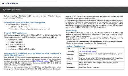
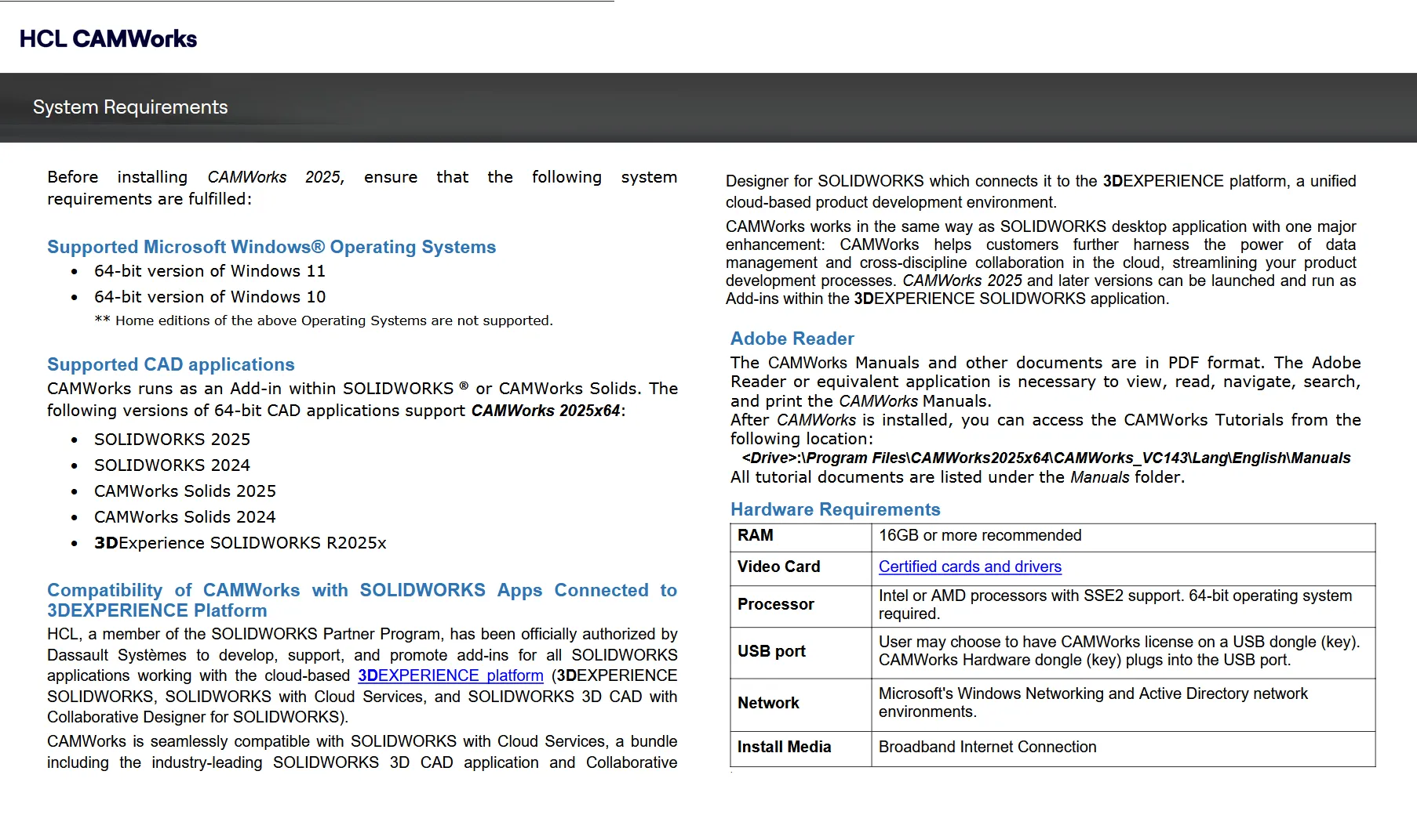
System Requirements: Windows *
Software Prerequisites: pre-installed SolidWorks 2024 - 2025
Size: 2.0 Gb
CAMWorks 2025 SP2 for SolidWorks
Please visit my blog
Added by 3% of the overall size of the archive of information for the restoration
No mirrors please

![CAMWorks 2025 SP2 for SolidWorks]()
Added by 3% of the overall size of the archive of information for the restoration
No mirrors please
CAMWorks 2025 SP2 for SolidWorks