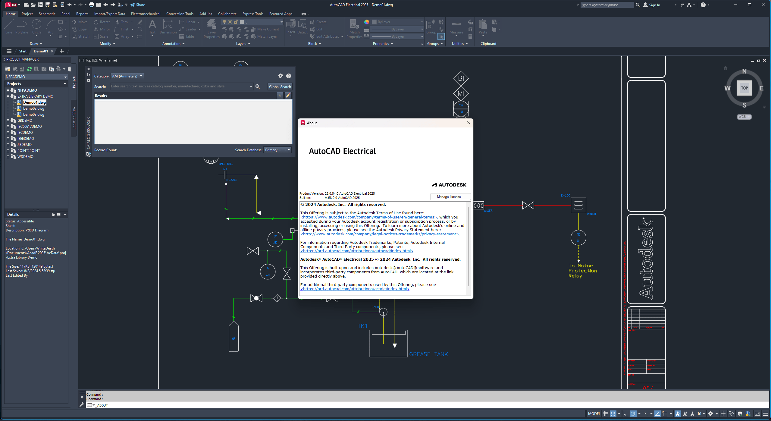
Autodesk AutoCAD Electrical 2025 with Offline Help | 4.4 Gb
Autodesk has released AutoCAD Electrical 2024 Toolset. Part of the Autodesk Digital Prototyping solution, AutoCAD Electrical is AutoCAD software for control designers, purpose-built to create and modify electrical control systems.
What's New in AutoCAD Electrical 2025 Toolset
Drawing List Report in Automatic Reports (What's New in 2025)
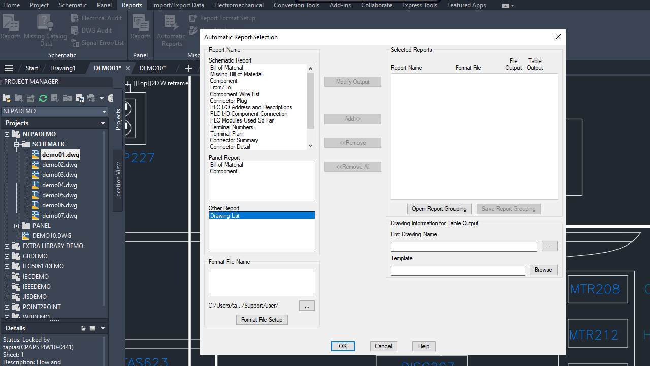
Easily create or update a drawing list report with the Automatic Reports tool. The Drawing List report provides valuable information by extracting and displaying the settings of each drawing within the project.
To create a drawing list report using the Automatic Reports tool:
1. Click Reports tabMiscellaneous panelAutomatic Reports.
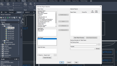
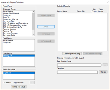
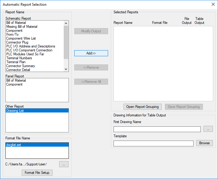
2. In the Automatic Report Selection dialog box, under Other Report, click Drawing List.
3. Choose a .set file.
If no .set file exists, click Format File Setup to create a new one.
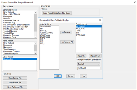
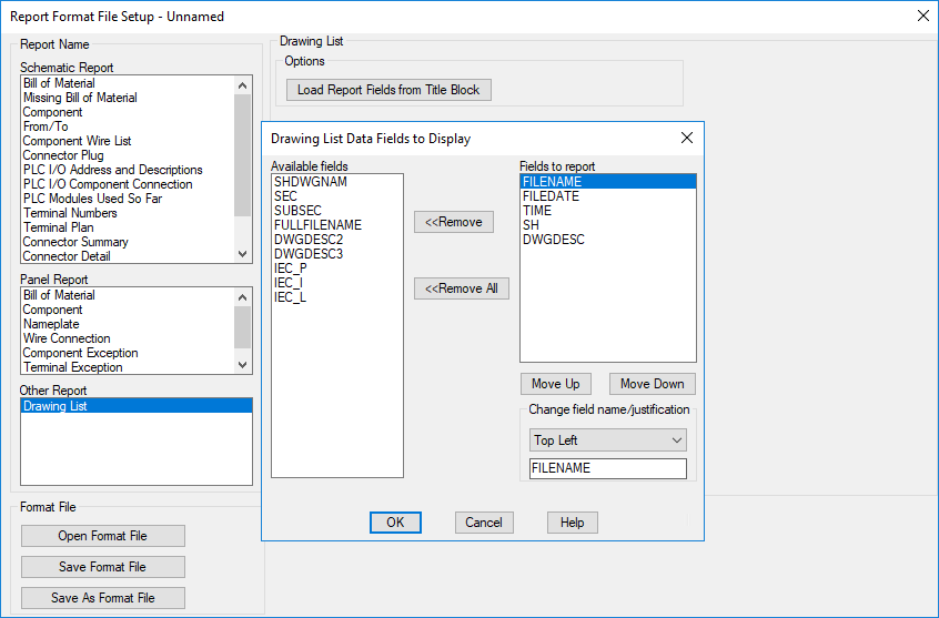
4. In the Report Format File Setup dialog box, click Change Report Fields to specify the report fields.
5. If you need additional fields from the title blocks, beyond the default options, click Load Report Fields from Title Block.
6. Click Change Report Fields.
7. (Optional) To specify which options to run when the report is generated, click User Post.
8. Click Save Report to File or Put on Drawing.
9. Click Save As Format File.
10. In the Select Drawing List file navigation dialog box, specify a name and click Save.
11. In the Report Format File Setup dialog box, click Done.
12. In the Automatic Report Selection dialog box, under Other Report, click Drawing List and select a .set file.
13. Click Add to add the Drawing List to Selected Reports list.
14. If necessary, add more reports to Selected Reports list.
Tip: Save the report grouping so you can easily run the specific group of reports whenever needed.
15. Click OK.
Important Notes
- When using the Automatic Reports tool, the Drawing List Report follows the sequence of drawings defined in the Project Manager.
- When you select Update Existing option in the Table Generation Setup dialog box (Format File SetupPut on Drawing), the existing drawing list report table is updated when Automatic Reports is run.
- When you select Insert New option in the Table Generation Setup dialog box (Format File SetupPut on Drawing), a new drawing is created and the drawing list report table is inserted when Automatic Reports is run.
Enhanced Sorting Options for Bill of Materials Report (What's New in 2025)
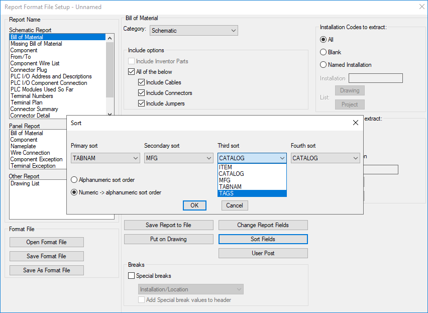
The Bill of Materials (BOM) report now offers an enhanced sorting capability by TAG, providing more control on how the BOM report is organized. In addition to the existing options for Schematic, Panel, and Automatic Reports, you can now sort the BOM report by TAG.
With the new TAG sorting option, you can easily group and categorize the BOM based on specific tags assigned to each component.
Furthermore, the sorting options have been expanded to include two types of sort orders:
- Alphanumeric
- Numeric to alphanumeric
To sort the Bill of Materials by tags:
1. Click Reports tab-Schematic panel-Reports.
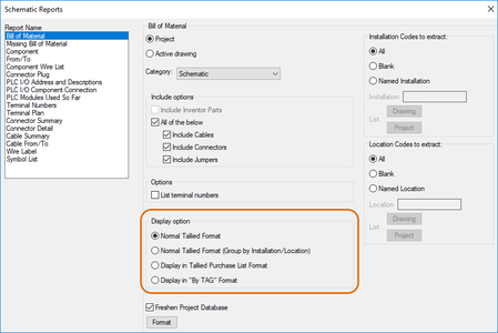
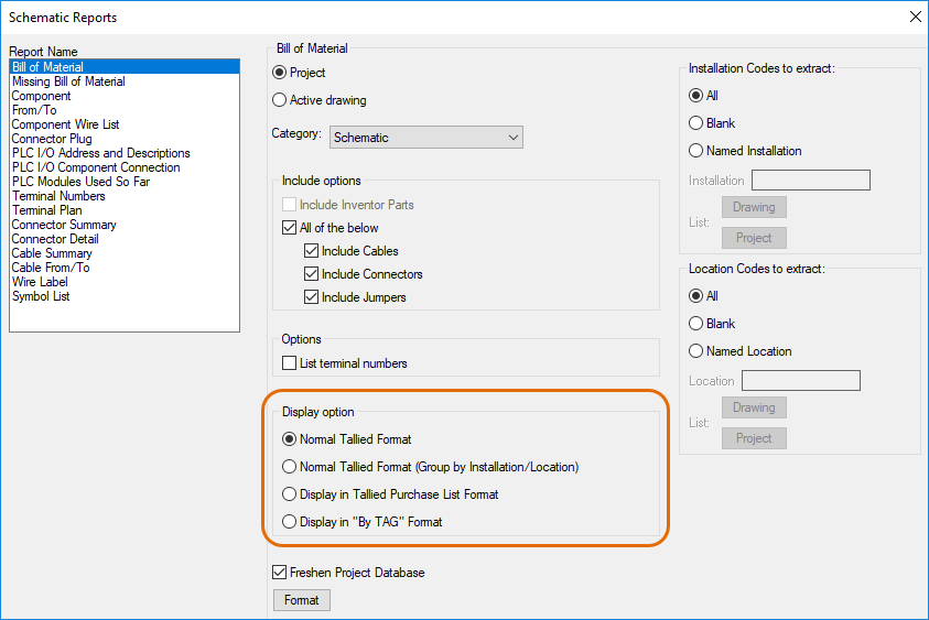
2. In the Schematic Reports dialog box, select Bill of Material from the report list.
3. Under Bill of Material, choose either Project or Active drawing.
4. Choose one from the following display options. Click OK.
5. In the Select Drawings to Process dialog box, select the required drawings and click Process, or click Do All to select all the drawings in a project. Click OK.
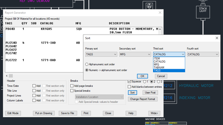
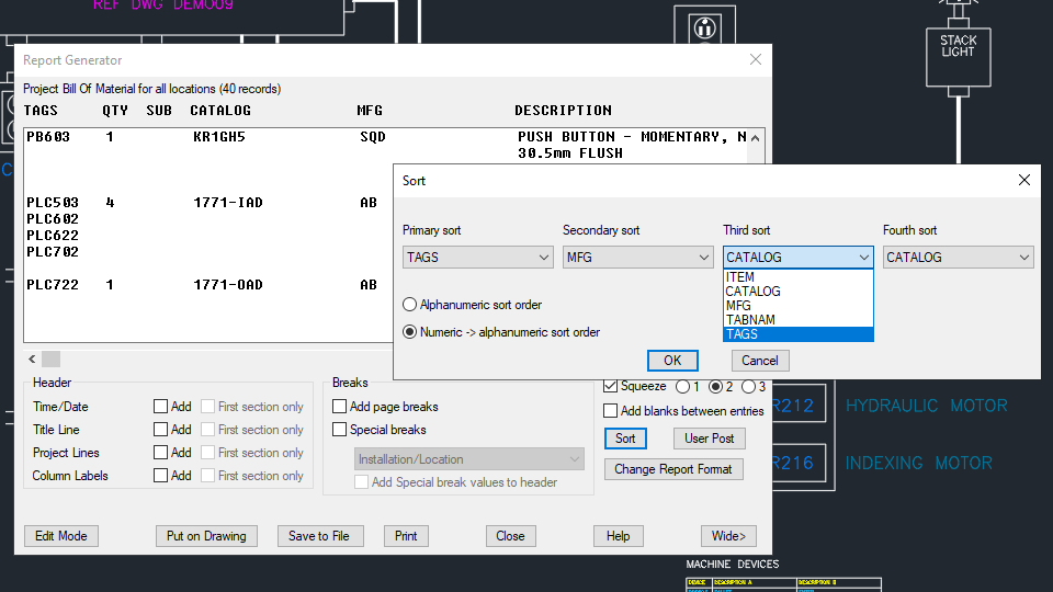
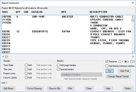
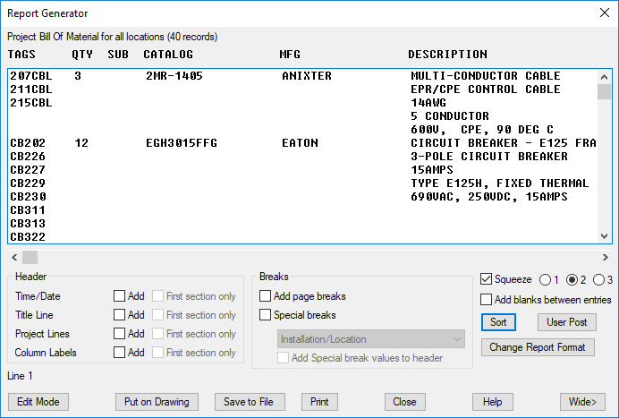
6. In the Report Generator dialog box, click Sort.
7. In the Sort dialog box, select the desired sort order for TAGS from the following options: Primary, Secondary, Third, or Fourth sort.
8. Specify whether to sort in alphanumeric or numeric to alphanumeric order. Click OK.
The Bill of Material is now sorted according to the selected options.
9. To insert the table into a drawing, click Put on Drawing.
Alternatively, click Save to File to save the table as the required file format.
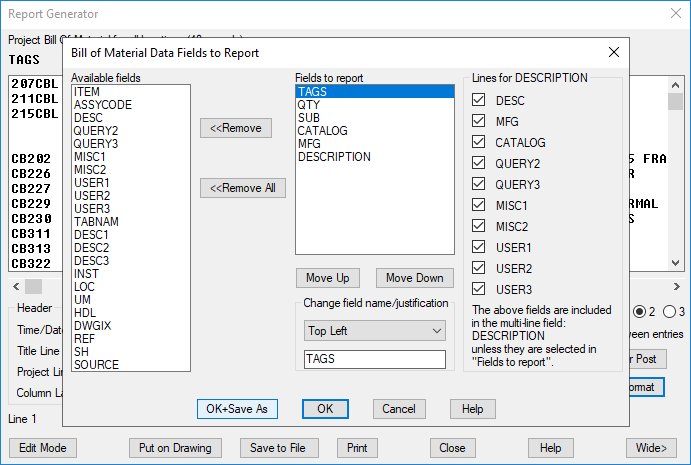
10. To save the selected sort options as a .set format file, click Change Report Format.
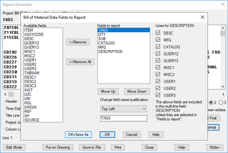
11. In the Bill of Materials Data Fields to Report, make necessary changes, if any. Click OK+Save As.
You can access the .set file in the main Schematic or Panel Reports dialog box.
Note: The .set file created using this dialog box is specifically intended for manual Schematic and Panel reports.
For automatic reports, create the .set file using the Report Format File Setup dialog box.
If you are using SET files from previous releases of AutoCAD Electrical toolset and require natural sorting, do the following:
1. Open the SET format file.
2. In the Sort dialog box, change the sorting option to Numericalphanumeric sort order option.
3. Save the SET format file.
Activity Insights (What's New in 2025)
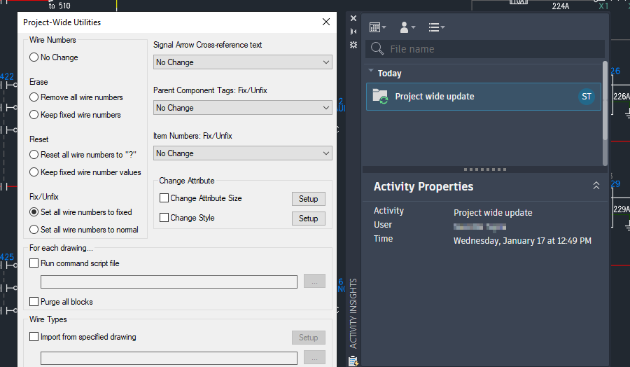
In AutoCAD Electrical 2025, the Activity Insights feature has been enhanced to provide more detailed information about events related to project-wide updates.
Project Wide Update Event
The Project-wide update event is only displayed for updates using the AEPROJUPDATE or AEUTILITIES commands.
Wire Type Synchronization (What's New in 2025)
In the previous release, when the wire type connected to the source arrows is updated, the wire type is synchronized for all destination wires in the network that share the same signal coe across multiple drawings. If the destination drawing does not contain the new wire type, new wire layers are automatically created along with their properties. However, if the wire layer already existed in the destination drawing when synchronized, any modified properties of the wire layer from the source were not propagated to the destination.
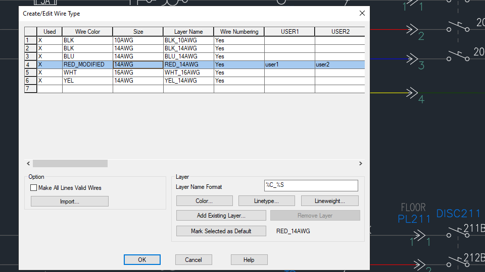
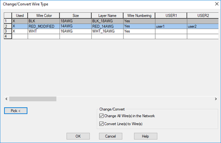
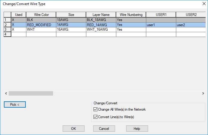
Now, when wire layer properties such as wire color, size, line weight, line type, and wire layer user attributes are modified, and the wire type is updated at the source arrow, the synchronization process ensures that all wire layer properties are overwritten in the destination wire layers from the source drawing.
To modify the wire layer properties and propagate to the destination:
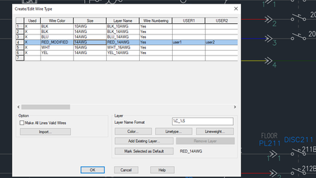
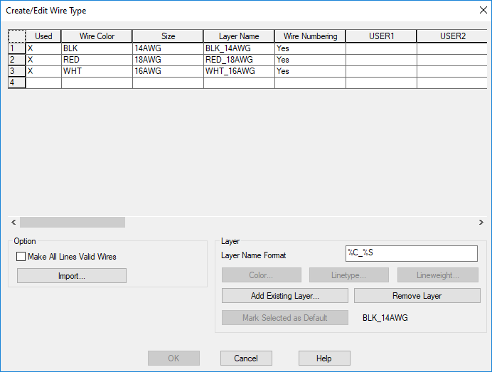
1. Click Schematic tab-Edit Wires/Wire Numbers panel-Modify Wire Type drop-down-Create/Edit Wire Type.
2. Choose the wire layer you want to modify in the source drawing.
3. Specify the properties such as wire color, size, line weight, line type, or user attributes. Click OK.
4. Check the wire layer properties in the destination drawing by clicking Schematic tab-Edit Wires/Wire Numbers panel-Modify Wire Type drop-down-Create/Edit Wire Type.
5. In the Create/Edit Wire Type dialog box, click Cancel.
6. Change the wire type of the source wire segment to a type different from the modified wire layer.
7. Now, change the source wire segment to the modified wire layer type. Click OK and update the destination wires.
The destination drawing wire layer type table is updated with the wire layer properties propagated from the source drawing.
Note: When propagating wire layer properties, including color changes, from the source drawing to the destination drawing, a save action is required in the destination drawing to reflect the color changes.
Autodesk AutoCAD is computer-aided design software that allows you to efficiently create and document 2D and 3D designs. Industry-specific Autodesk tools, such as architecture, plant 3D, map 3D, MEP, electrical, mechanical and grid design, make Autodesk AutoCAD the number one software for architects, engineers and construction professionals.
Autodesk AutoCAD 2025 enhances your 2D and 3D design experience with features that unlock insights and automations with the help of Autodesk AI, tailors to discipline-specific workflows, and stay connected with one experience on desktop, web, and mobile—to capture, share, and review ideas on the go.
Autodesk combined seven industry-specialized toolsets into one version of AutoCAD, and one of those is the Electrical toolset. With the Electrical toolset, you can access a library of 65,000+ intelligent electrical symbols; automate the numbering of wires and generation of component tags and generate and update multiple customized reports automatically.
AutoCAD Electrical Tutorial for Beginners - 1
AutoCAD Electrical Tutorial for Beginners - 2
Autodesk helps people imagine, design and create a better world. Everyone—from design professionals, engineers and architects to digital artists, students and hobbyists—uses Autodesk software to unlock their creativity and solve important challenges.
Owner: Autodesk Inc.
Product Name: AutoCAD Electrical Toolset
Version: 2025.0 with Offline Help
Supported Architectures: x64
Website Home Page : www.autodesk.com
Languages Supported: multilanguage
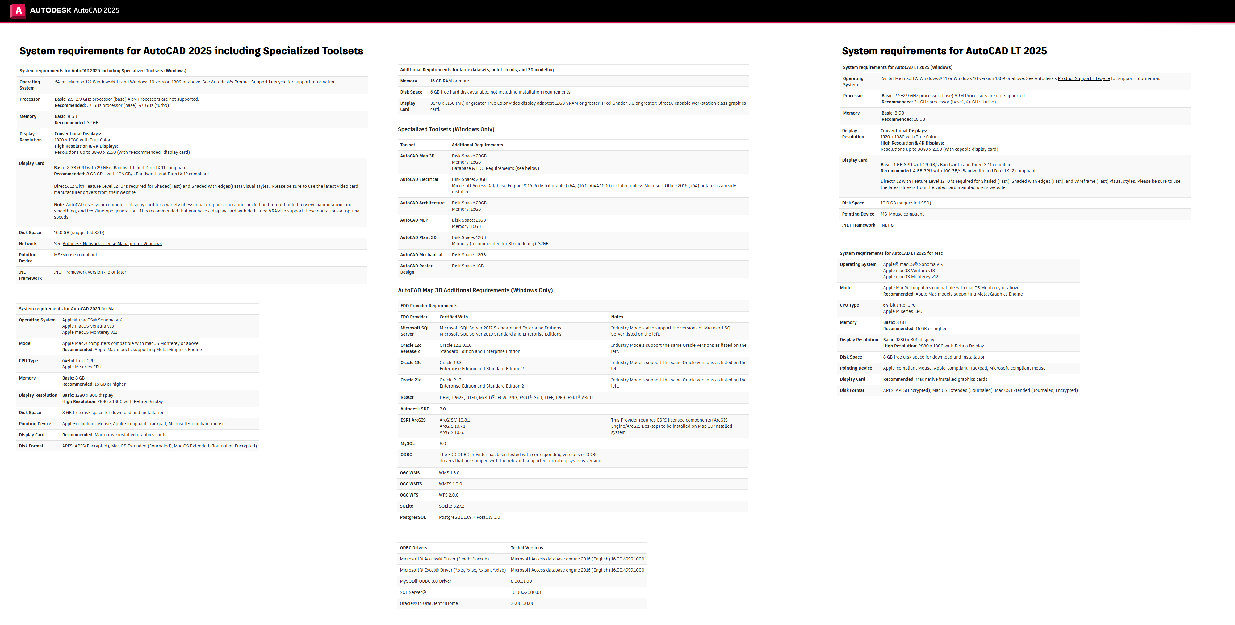
System Requirements: Windows *
Size: 4.4 Gb
Please visit my blog
Added by 3% of the overall size of the archive of information for the restoration
No mirrors please
Added by 3% of the overall size of the archive of information for the restoration
No mirrors please


